Page 848 - techequipmentscatalogue2016
P. 848
IR
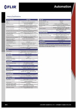
Imaging Specifications
System Overview FLIR A31D Ethernet IEEE B023
Spotmeter 10 Ethernet, standard RJ-45
Area Ethernet, connector type
Isotherm 10 boxes with max./min./average/position Ethernet, type 100 Mbps
1 with above/below/interval Ethernet, communication TCP/IP socket-based FLiR proprietary
Measurement option Measurement Mask Filter Ethernet, power Power over Ethernet, PoE IEEE B02.3af class 0
Ethernet
Difference temperature Schedule response: File sending (ftpJ. email (SMTPI Control, result and image
Delta temperature between measurement functions Ethernet, protocols Ethernet/IP, Modbus TCP, TCP, UDP, SNTP, RTSP,
Reference temperature RTP, HTTP, ICMP, IGMP, ftp, SMTP, 5MB (CIFSJ.
or reference temperature Ethernet, image streaming
Atmospheric transmission correction Manually set or captured from any measurement DHCP, MDNS (Bonjour), uPnP
Optics transmission correction fu ncti on 16-bit 320 x 240 pixels at 7-8 Hz
Emissivity correction Automatic, based on inputs for distance, atmospheric -Radiometric
Reflected apparent
temperature correction temperature and relative humidity Environmental data -40°C to +70°C (-40° to 15BOF)
Automatic, based on signals from internal sensors Storage temperature range
External optics/windows correction Humidity (operating and storage) IEC 60068-2-30/24 h 95% relative humidity
Variable from 0.01 to 1.0 +25°C to +40°C (77 to 104°F)
Measurement corrections EMC
Field of view (FOV) / Automatic, based on input of reflected temperature • EN 61000-6-2:2001 (Immunity)
Minimum focus distance ..Vibration • EN 61000-6-3:2001 (Emission)
Lens identification Automatic, based on input of optics/window • FCC 47 CFR Part 15 Class B (Emission)
Thermal sensitivity/NETD transmission and temperature
Focus 2 g (I EC 60068-2-6)
F-number Global and individual object parameters
Image frequency .Housing material I Aluminium
25° x 1B.Bo / 0.4 m (1.31 ftl
Zoom o• • 0 -
Automatic
Cardboard box, Infrared camera with lens, Ethernet cable, FLiR Tools download card,
Automatic or manual (built in motor) Mains cable, Power cable - pig-tailed, Power supply, Printed documentation, User
1.3 documentation CD-ROM, Utility CD-ROM
30 Hz
1-Bx continuous, digital, interpolating zooming
on Ima es
Alarm functions 6 automatic alarms on any selected measurement
function, Di ital ln, Camera temperature, timer
Alarm output
Digital Out, log, store image, file sending (ftp), email
Detector data (SMTPJ. notification
IR resolution
Detector pitch 320 x 240 pixels
Detector time constant
Focal Plane Array (FPA) / 25~m
Spectral range
Typical 12 ms
Uncooled microbolometer / 7.5-13 ~m
Object temperature range -20 to +120°C (-4 to 24BOF)
Accuracy
oto +350°C (32 to 662°F)
±2°C (3 .6°F) or ±2% of reading
Color palettes Color palettes (BW, BW inv, Iron, Rain)
Set-u commands Date/time, Tem erature °C;oF
Image storage type Built-in memory for image storage
File formats
Standard JPEG, 16-bit measurement data
included
Video out Composite video output, PAL and NTSC
compatible
Video, standard
CVBS (ITU-R-BT.470 PAL/SMPTE 170M NTSC)
I• .
2 opto-isolated, 10-30 VDC
Digital input As function of ALARM, Output to ext. device
Digital output, purpose (programmatically set)
2 opto-isolated, 10-30 VDC, max 100 mA
Digital output
Digital I/O, isolation voltage 500VRMS
Digital I/O, supply voltage 12/24 VDC, max 200 mA
Digital I/O, connector type 6-pole jackable screw terminal
Image tag (start/stop/general), Input ext. device
Digital input, purpose (pro rammaticall read)
842 www.tech-equipments.comlsales@tech-equipments.com