Page 850 - techequipmentscatalogue2016
P. 850
IR
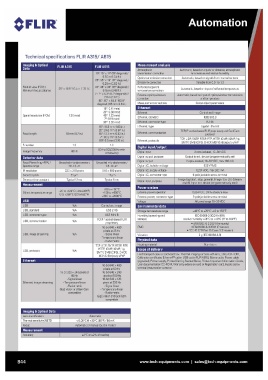
Technical specifications FLiR A315/ A615
Imaging &Optical FLiR A315 FLiR A615 Measurement analysis
Data Atmospheric
25° x 18.8° /0.4 m (1.31 ft.) 15°: 15° x 11° (19° diagonal) / transmission correction Automatic, based on inputs for distance, atmospheric
Field of view (FOV) / 0.50 m (1.64 ft) Optics transmission correction temperature and relative humidity
Minimum focus distance 1.36 mrad Emissivity correction
18 mm (0.7 in) 25°: 25° x 19° (31 ° diagonal) / Reflected apparent Automatic, based on signals from internal sensors
Spatial resolution IIFOV) 0.25 m (0.82 ft.) temperature correction Variable from 0.01 to 1.0
1.3 External optics/windows
Focal length 60 Hz 45°: 45° x 34° (55° diagonal) / correction Automatic, based on input of reflected temperature
0.15 m (049 ft.) Measurement corrections
F-number Ethernet Automatic, based on input of optics/window transmission
Image frequency 7°: 7" x 5.3° (87" diagonally) / Ethernet and temperature
Detector data 2.0 m (66 ft) Ethernet, standard
Focal Plane Array (FPA) / Ethernet, connector type Global object parameters
Spectral range 80°: 80° x 644° (92.8° Ethernet, type
IR resolution diagonal) / 65 mm (2.6 in) Control and image
Detector pitch Ethernet, communication IEEE802.3
Detector time constant 15°: 041 mrad RJ-45
25°: 0.68 mrad Ethernet, protocols
45°' 1.23 mrad Gigabit Ethernet
7": 0.19mrad Digital input/output TCP/IPsocket-based FUR proprietary and Gen lCam
80°: 2.62 mrad Digital input
Digita l output, purpose protocol
15°: 41.3 mm (1.63 in.) Digital output TCP, UDP, SNTP, RTSP, RTP, HTTP, ICMP, IGMP, ftp,
25°' 24.6 mm (097 in.) Digita l I/O, isolation voltage
45°: 13.1 mm (052 in.) Digital I/O, supply voltage SMTP, 5MB (C IFS)' DHCP, MDNS (Bonjour), uPnP
7": 88.9 mm (3.5 in.) Digita l I/O, connectortype
80° 6.5 mm (0.26 in) 2 opto-isolated, 10-30 VDC
Output to ext. device (programmatically set)
1.0 2 opto-isolated, 10-30 VDC, max 100 mA
50 Hz (100/200 Hz with 500VRMS
windowing) 12/24 VDC, max 200 mA
6-pole jackable screw terminal
Uncooled microbolometer / Uncooled microbolometer / Image tag (start, stop, general)' Image flow ctrl. (Stream
75-13 ~m 7.5-14 ~m on/off), Input ext. device (programmatically read)
320 x 240 pixels 640 x 480 pixels
25~m 17~m
Typical 12 ms Typical 8 ms
USB N/A Control and image IEC 60068-2-30/24 h 95%
USB, standard N/A relative humidity +25°Cto +40°C(77 to 104°F)
USB, connector type N/A USB 2 HS
USB, communication N/A • EN 61000-6-2:2001 (Immunity)
USB Mini-B EMC • EN 61000-6-3:2001 (Emission)
USB, image streaming N/A
TCP/IP socket-based FUR • FCC 47 CFR Part 15 Class B (Emission)
USB, protocols N/A proprietary
Ethernet Vibration 2 g (IEC 60068-2-6)
16-bit 320 x 240 pixels at 16-bit 640 x 480
Ethernet, image streaming 60 Hz pixels at 25 Hz Physical data
- Signal linear
- Signal linear - Temperature linear ~~
- Temperature linear - Radiometric
Scope of delivery
- Radiometric TCP, UDP, SNTP, RTSP, RTP,
GigE Vision and GenlCam HTTP, ICMP, IGMP, ftp, Hard transport case or cardboard box, Thermal imaging camera with lens, Utility CD-ROM,
Calibration certificate, Ethernet™ cable, USB cable (FUR A615)' Mains cable, Power cable
compatible SMTP, 5MB (CIFS)' DHCP, (pig-tailed)' Power supply, Printed Getting Started Guide, Printed Important Information Guide,
MDNS (Bonjour), uPnP User documentation CD-ROM, Warranty extension card or Registration card, 6-pole screw
terminal (mounted on camera)
16-bit 640 x 480
pixels at 50 Hz
16-bit 640 x 240
pixels at 100 Hz
16-bit 640 x 120
pixels at 200 Hz
- Signal linear
- Temperature linear
- Radiometric
GigE Vision and GenlCam
compatible
844 www.tech-equipments.comlsales@tech-equipments.com