Page 862 - techequipmentscatalogue2016
P. 862
IR
Technical specifications
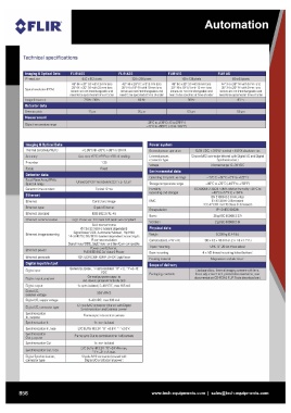
Imaging &Optical Data FLIR AS5 FLIR A35 FLIR A15 FLIR A5
Spatial resolution (lFOV) 640 x 512 pixels 320 x 256 pixels 160 x 128 pixels 80 x 64 pixels
45' (H) x 37' (V) with 13 mm lens 48' (H) x 39' (V) with 9 mm lens 48' (H) x 39' (V) with 9 rnm lens 44' (H) x 36' (V) with 5 mrn lens
25' (H) x 20' (V) with 25 mm lens
25' (H) x 19' (V) with 19 mm lens 25' (H) x 19' (V) with 19 mm lens 25' (H) x 20' (V) with 9 mm lens
lenses are not interchangeable and lenses are not interchangeable and lenses are not interchangeable and
need to be at time 01 order need to be at time 01 order need to be at time 01 order
Imaging & Optical Data < 0.05'C @+30'C (+86'F) / 50 mK Power system 12/24 VDC, < 3.5 W nominal < 6.0 W absolute max
Thermal sensitivity/NETD External power operation 12-pole M12 connector (shared with Digital I/O and Digital
External power,
connector type Synchronization)
Voltage Allowed range 10-30 VDC
Environmental data
Operating temperature range - 15'C to +50' C (+5'F to +122' F)
Storage temperature range
Humidity -40'C to +70' C (-40'F to +158' F)
(operating and storage) IEC 60068-2-30/24 h 95% relative humidity +25'C to
EMC +40' C (+77°F to +104'F)
EN 61000-6-2 (Immunity)
Encapsulation EN 61000-6-3 (Emission)
Bump FCC 47 CFR Part 15 Class B (Emission)
Vibration
Physical data IP 40 (l EC60529)
25 g (l EC60068-2-27)
2 g (I EC 60068-2-6)
Ethernet. image streaming 8-bit monochrome Packaging, contents
@7.5 / 30 / 60 Hz (variant dependant)
Ethernet. power Signal linear/ DDE, Automatic/ Manual, Flip H&V
14-bit@7.5 / 30 / 60 Hz (variant dependent) according to
Ethernet, protocols
Digital input/output IRcamera resolution
Digital input Vision and GenlCam
Digital output, purpose Power over Ethernet,
PoE IEEE 802.3al ctass 0 Power
Digital output TCP, UDP, ICMP, IGMP, DHC P, GigEVision
Digital I/O,
isolation voltage General purpose, lx opto-isolated, "0" < 2, "1 ";2-12
Digital I/O, supply voltage VDC
Digital I/O, connector type General purpose output to
Synchronization ext. device (programmatically set)
In, purpose 1x opto-isolated, 2- 40 VDC, max 185 mA
Synchronization In
Synchronization In, type 500VRMS
Synchronization
Out, purpose 2-40 VDC, max 200 mA
Synchronization Out 12-pole M12 connector (shared with Digital
Synchronization Out, type Synchronization and External power)
Digital Synchronization,
connector type Frame sync In to control camera
lx, non-isolated
LVC Buffer@3.3V, "0" <0.8 V, "1 ">2.0 V.
Frame sync Out to control another Ax5 camera
lx, non-isolated
LVC Buffer@3.3V, "0"; 24 MA max,
"1"; - 24 mA max.
12-pole M12 connector (shared with
Digital I/O and External power)
856 www.tech-equipments.comlsales@tech-equipments.com
Technical specifications
Imaging &Optical Data FLIR AS5 FLIR A35 FLIR A15 FLIR A5
Spatial resolution (lFOV) 640 x 512 pixels 320 x 256 pixels 160 x 128 pixels 80 x 64 pixels
45' (H) x 37' (V) with 13 mm lens 48' (H) x 39' (V) with 9 mm lens 48' (H) x 39' (V) with 9 rnm lens 44' (H) x 36' (V) with 5 mrn lens
25' (H) x 20' (V) with 25 mm lens
25' (H) x 19' (V) with 19 mm lens 25' (H) x 19' (V) with 19 mm lens 25' (H) x 20' (V) with 9 mm lens
lenses are not interchangeable and lenses are not interchangeable and lenses are not interchangeable and
need to be at time 01 order need to be at time 01 order need to be at time 01 order
Imaging & Optical Data < 0.05'C @+30'C (+86'F) / 50 mK Power system 12/24 VDC, < 3.5 W nominal < 6.0 W absolute max
Thermal sensitivity/NETD External power operation 12-pole M12 connector (shared with Digital I/O and Digital
External power,
connector type Synchronization)
Voltage Allowed range 10-30 VDC
Environmental data
Operating temperature range - 15'C to +50' C (+5'F to +122' F)
Storage temperature range
Humidity -40'C to +70' C (-40'F to +158' F)
(operating and storage) IEC 60068-2-30/24 h 95% relative humidity +25'C to
EMC +40' C (+77°F to +104'F)
EN 61000-6-2 (Immunity)
Encapsulation EN 61000-6-3 (Emission)
Bump FCC 47 CFR Part 15 Class B (Emission)
Vibration
Physical data IP 40 (l EC60529)
25 g (l EC60068-2-27)
2 g (I EC 60068-2-6)
Ethernet. image streaming 8-bit monochrome Packaging, contents
@7.5 / 30 / 60 Hz (variant dependant)
Ethernet. power Signal linear/ DDE, Automatic/ Manual, Flip H&V
14-bit@7.5 / 30 / 60 Hz (variant dependent) according to
Ethernet, protocols
Digital input/output IRcamera resolution
Digital input Vision and GenlCam
Digital output, purpose Power over Ethernet,
PoE IEEE 802.3al ctass 0 Power
Digital output TCP, UDP, ICMP, IGMP, DHC P, GigEVision
Digital I/O,
isolation voltage General purpose, lx opto-isolated, "0" < 2, "1 ";2-12
Digital I/O, supply voltage VDC
Digital I/O, connector type General purpose output to
Synchronization ext. device (programmatically set)
In, purpose 1x opto-isolated, 2- 40 VDC, max 185 mA
Synchronization In
Synchronization In, type 500VRMS
Synchronization
Out, purpose 2-40 VDC, max 200 mA
Synchronization Out 12-pole M12 connector (shared with Digital
Synchronization Out, type Synchronization and External power)
Digital Synchronization,
connector type Frame sync In to control camera
lx, non-isolated
LVC Buffer@3.3V, "0" <0.8 V, "1 ">2.0 V.
Frame sync Out to control another Ax5 camera
lx, non-isolated
LVC Buffer@3.3V, "0"; 24 MA max,
"1"; - 24 mA max.
12-pole M12 connector (shared with
Digital I/O and External power)
856 www.tech-equipments.comlsales@tech-equipments.com