Page 978 - techequipmentscatalogue2016
P. 978
UKE ®
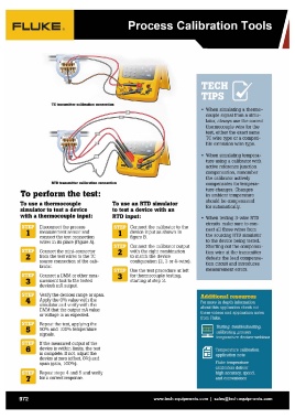
TC transmiHer calibration connection
RTD transmiHer calibration connection • When simulating a thermo-
couple signal from a simu-
To perform the test: To use an RTD simulator lator, always use the correct
to test a device with an thermocouple wire for the
To use a thermocouple test, either the exact same
simulator to test a device RTD input: TC wire type or a compati-
with a thermocouple input: ble extension wire type.
Disconnect the process 1 Connect the calibrator to the • When simulating tempera-
measurement sensor and device input as shown in ture using a calibrator with
connect the test connection "'---_oJ figure B. active reference junction
wires in its place (Figure A). compensation, remember
2"'""11,,,:,.1 Connect the calibrator output the calibrator actively
Connect the mini-connector with the right combination compensates for tempera-
from the test wires to the TC '----' to match the device ture changes. Changes
source connection of the cali- in ambient temperature
brator. configuration (2, 3 or 4-wire) . should be compensated
for automatically.
Connect a DMM or other mea- 3H~~ Use the test procedure at left
surement tool to the tested for thermocouple testing, • When testing 3-wire RTD
device's rnA output. '---..I starting at step 3 . circuits make sure to con-
nect all three wires from
Verify the devices range or span. the sourcing RTD simulator
Apply the 0% value with the to the device being tested.
simulator and verify with the Shorting out the compensa-
DMM that the output rnA value tion wire at the transmitter
or voltage is as expected. defeats the lead compensa-
tion circuit and introduces
Repeat the test, applying the measurement errors.
50% and 100% temperature
signals. Additional resources
If the measured output of the For more in depth information
device is within limits, the test about this application check out
is complete. If not, adjust the these videos and application notes
device at zero (offset, 0%) and from Fluke.
span (gain, 100%).
Testing, troubleshooting,
7 Repeat steps 4 and 5 and verify calibrating process
for a correct response. temperature devices webinar
Temperature calibration
application note
Fluke temperature
calibrators deliver
high accuracy, speed,
and convenience
972 www.tech-equipments.comlsales@tech-equipments.com