Page 982 - techequipmentscatalogue2016
P. 982
UKE ®
To perform the test: • When testing the tempera-
ture switch, the applied
To use a thermocouple simulator to test a switch temperature should agree
with a thermocouple input: with the temperature
displayed on the controller
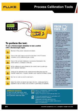
Disconnect the process measurement sensor. or switch's display. If it does
not agree, the device's
Connect the mini-connector from the test wires to the TC source input A/D may need
adjustment per manufactur-
2 connection of the calibrator (figure above). er's procedure.
Connect the calibrator resistance measurement terminals to the • When testing a switch
with damping (delay of
3 switch contacts to measure continuity. output change for a change
on the input) set, it might
Set the calibrator to source/simulate the correct thermocouple type be necessary to test the
switch manually by slowly
4 and to measure resistance. changing the temperature
in small tests.
Configure the calibrator for the switch test describing the expected
setpoint temperature, allowable deviation and expected deadband values. • When testing a mechanical
temperature switch (no
Run the test and evaluate the test results. external sensor), use a field
temperature bath calibrator
Adjust the switch as needed and repeat the test confirming that the for best results.
adjustment was successful and the switch is performing as expected.
• To test live switch contacts
switching 24 V dc or 120-
240 V ac, select a calibrator
that can measure these live
voltages, such as the Fluke
75X family of Documenting
Process Calibrators.
Most other temperature
calibrators can only
measure continuity changes
when testing switches.
976 www.tech-equipments.comlsales@tech-equipments.com
To perform the test: • When testing the tempera-
ture switch, the applied
To use a thermocouple simulator to test a switch temperature should agree
with a thermocouple input: with the temperature
displayed on the controller
Disconnect the process measurement sensor. or switch's display. If it does
not agree, the device's
Connect the mini-connector from the test wires to the TC source input A/D may need
adjustment per manufactur-
2 connection of the calibrator (figure above). er's procedure.
Connect the calibrator resistance measurement terminals to the • When testing a switch
with damping (delay of
3 switch contacts to measure continuity. output change for a change
on the input) set, it might
Set the calibrator to source/simulate the correct thermocouple type be necessary to test the
switch manually by slowly
4 and to measure resistance. changing the temperature
in small tests.
Configure the calibrator for the switch test describing the expected
setpoint temperature, allowable deviation and expected deadband values. • When testing a mechanical
temperature switch (no
Run the test and evaluate the test results. external sensor), use a field
temperature bath calibrator
Adjust the switch as needed and repeat the test confirming that the for best results.
adjustment was successful and the switch is performing as expected.
• To test live switch contacts
switching 24 V dc or 120-
240 V ac, select a calibrator
that can measure these live
voltages, such as the Fluke
75X family of Documenting
Process Calibrators.
Most other temperature
calibrators can only
measure continuity changes
when testing switches.
976 www.tech-equipments.comlsales@tech-equipments.com